|
I'm currently working on a number of small projects in connection with the restoration of an old motor yacht, which is based in the South of France. The latest of these is the refurbishment
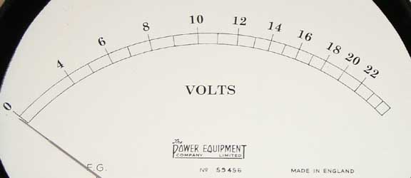
of an old voltmeter to be used to monitor the state of the ships
battery supply. The meter selected was rather odd. It
was equipped with side terminals as well as the usual rear terminals
and was clearly designed to be used a portable instrument, possibly
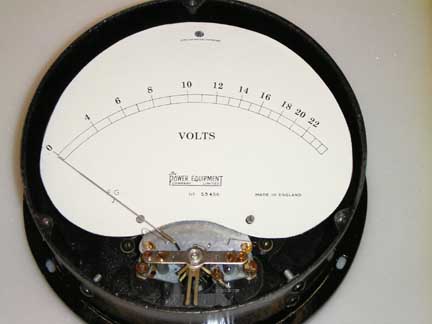
in a power station. I had at first assumed that the meter could be modified to change the full-scale deflection from 30-volts to something less. This requirement stemmed from the idea that it would be better to have a central range of readings for normal operation rather than say third scale. Imagine my thoughts then when I discovered that no external series resistor was incorporated to set the scale to 30-volts. Moving iron meters are totally different
to moving coil. A moving iron meter uses a solenoid through the
centre of which is located the pair of iron plates comprising
part of the pointer mechanism. When a magnetic field is established
in the solenoid the two plates repel each other and in so doing
set the pointer to a particular reading. Initially I imagined that merely adding extra turns to the coil would provide the answer but after some experimentation I found that the space available for additional wire, in a gauge convenient for experimentation, was insufficient and I was faced with having to use very thin wire for the extra turns, or to make a new solenoid. As I didn't have a ready supply of enamelled wire of the right gauge I decided to cannibalise an old mains transformer that had already been hacked around in another project and discarded. The first task was to remove the laminations so I could get to the wire, which I vaguely planned to wind on top of the old solenoid. Getting out old laminations is sometimes easy… they just drop out. This transformer was not in that category however and I ended up hacksawing, chiselling and punching them out. Even the last one needed quite a bashing to remove it. The next step was to remove the old secondary winding. That done I looked at the end result. The bobbin on which the primary was wound looked about the same size as the old solenoid. I imagined that the fact that it was square rather than round might not matter so much. A few minutes later I'd established the fact that the new solenoid actually produced a deflection of about 20-volts. This being the case I wouldn't have to mess around adding extra wire to the original, with a few mechanical modifications I could use the new bobbin. To preserve the old parts, I traced round the old ebonite mounting plate and made a duplicate from Perspex on which to mount the new solenoid. After a lot of careful drilling and filing it was in place and I was pleased to see that the centre area of the scale was now exactly as required. I tidied up the mechanical aspects and considered the steps required to make a new scale. Previously I'd used a neat little program downloaded from a US website, but as luck would have it, the maximum parameters for the scale design were inadequate. The maximum size of the end result would be only 75% of what I needed. I decided therefore to scan the old scale and process it on the computer to keep the interesting old markings but to blank out and replace the numerals. This would result in a much more authentic end result than messing around scanning and pasting the old markings into the US program. The new approach turned out to be relatively easy and with assistance from my younger son, versed in the mysteries of Photoshop's advanced features, we produced a new scale that looked exactly the part. |
|
It all sounds simple and straightforward but of course it wasn't. Part of the process was calibration. Moving iron meters are very non-linear and can be very cramped at the high end of the scale. It took more than a few attempts to get the calibration right and to make final adjustments to the artwork. Also as part of the equation I had to deal with the words written across the top of the scale "use horizontally". The newly refurbished meter was to be used in a vertical position. Although the needle assembly was counterbalanced there must by necessity be some variation in its movement, associated with the effects of gravity. Calibration had to made therefore with the movement in a vertical orientation. During the calibration exercise I discovered hysteresis effects. Pointer position was affected by the fact that one could be applying more voltage across the terminals or less voltage. Smoothly increasing the voltage and making calibration marks was 't good enough as I found that backing off from full scale and checking these resulted in discrepancies. Waggling the voltage up and down seemed to result in a good average and it was this technique I used for final calibration. How could I ensure that 12-volts in the chill of the New Forest in spring would produce the same exact reading in the heat of high summer in the South of France? I couldn't. However I realised a simple device was available for this purpose. The meter is equipped with a zeroing lever. Normally this is used to set the pointer to zero when there is no voltage applied, but in its new application this feature is really redundant. It is therefore a simple matter then to apply a known voltage of around 12 to the terminals when the meter is in its final location and to set the zeroing lever to precisely this voltage. This will be done at a representative temperature and will result in very accurate readings over the expected variation of a charging 12-volt battery system. The original condition of the case of the old meter was typical for its age (mainly rusty) but, after lightly rubbing down with fine emery, several thin coats of smooth black hammerite resulted in the right looks. No signs of rust but still old looking. The front was typical of early meters being finished in a kind of uniform black pebbledash for want of a better description. Several coats of hammerite resulted in a glossy finish to the pebbledash that will keep the ravages of salt laden atmosphere at bay. |
 |
 |