 |
|
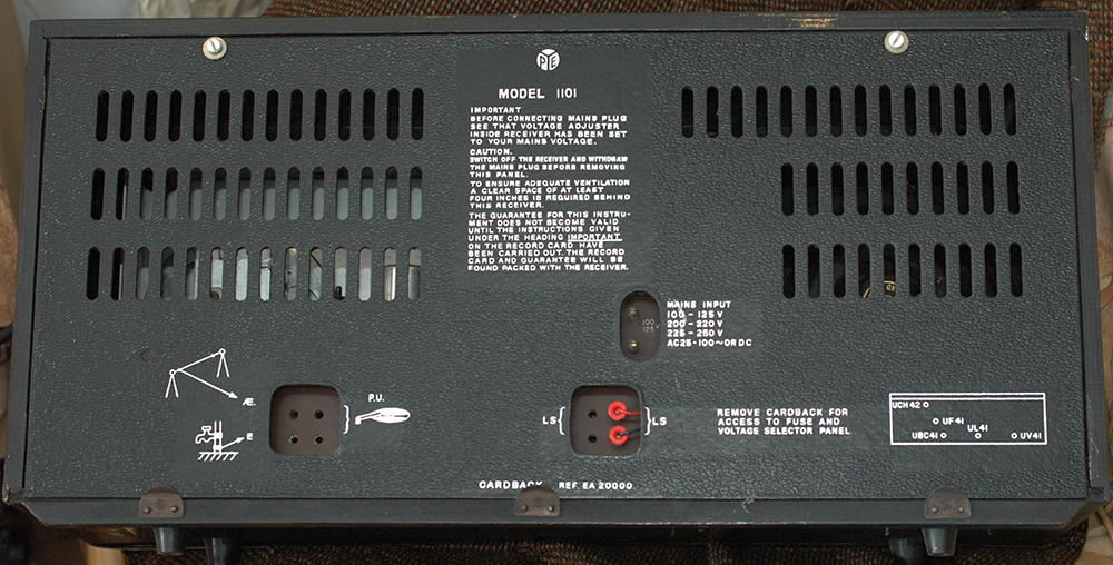
This rather large radio was made
in 1963 and has a set of valves designed for heater series connection
because it's for use on so-called universal mains. Most TV sets
were also "universal". I suspect the term was valid
in the 1930s and 1940s and rarely in the early 1950s but, because
DC mains was long gone by the time this set was manufactured,
the elimination of the cost of a mains transformer made universal
sets more profitable.
There are no less than seven shortwave
bands as well as the usual long and medium wavebands. This was
in those days of exotic reception with most stations having their
own musical jingle. |
 |
|
You'll notice the set has a two-pin
mains connector which meant that its reversal would make the
chassis sit at 240 volts above earth. In fact the back appears
to be shaped to prevent reversal of the plug, but what about
the other end of the mains cable? Many households used a bayonet
adaptor plugged into a two way ceiling adaptor or a two-pin mains
socket and those who had a three-pin round connector probably
wouldn't check which wire was connected to the chassis anyway.
The fact that the pins are not marked plus/minus meant that even
if you did have DC mains would have resulted in confusion. I
suppose the "Instructions" mentioned on the rear cover
might have explained everything? |
 |
|
The valves are from left to right:
UCH41 frequency changer, behind the IF can a UF41 IF amplifier,
a UBC41 detector/AVC and audio amplifier, a UL41 output stage
and a half-wave diode rectifier, UY41. These are all B8A based
valves with a common heater current of 200mA connected in series
to trhe mains via a ballast resistor. Because the set is designed
for 100 to 250 volts this ballast resistor has several tapping
points selected by the plug-in switch arrangement below the pair
of fuses. Two fuses so that if the chassis was earthed one would
be garanteed to blow no matter which way round the mains was
wired.. |
 |
There are two license plates.. this
one is nailed to the inside of the case. |
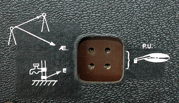 |
A graphic almost showing how to wire
up the aerial, earth and gram pick-up. OK if the set was in the
kitchen or, god forbid the bathroom, it's easy to connect to
a tap, otherwise how would you do this? |
|
|
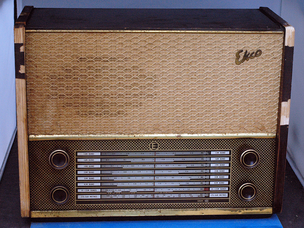
Ekco
Model U723/1
|
 |
|
This set is not very common
and may have been made for export as it has no long waveband,
but instead a range of bandspread short wavebands. From the examples
I've spotted a weakness is the veneer, which turns brittle and
is easily broken off. My guess is that it was made around 1959. |
 |
 |
 |
|
The receiver is not fitted with a
mains transformer so would have worked on AC or DC mains. The
valve line up is shown on the picture of the label and these
are loctal types with heaters designed for series operation in
conjunction with that vertical green ballast resistor. Note the
rather large bayonet type of dial lamp which will have a filament
in keeping with the spec of the valve heaters and might prove
awkward to replace if it were to fail. The voltage-setting adjuster
shows a wide range of potential power sources and of course the
mains lead being a two wire cable makes it possible to have a
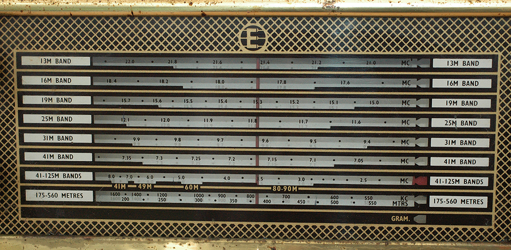
live chassis. The frequency coverage shown below looks rather
odd given the accuracies quoted. |
 |
|